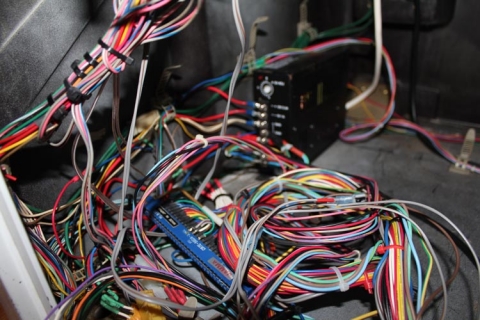
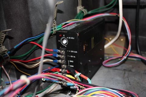
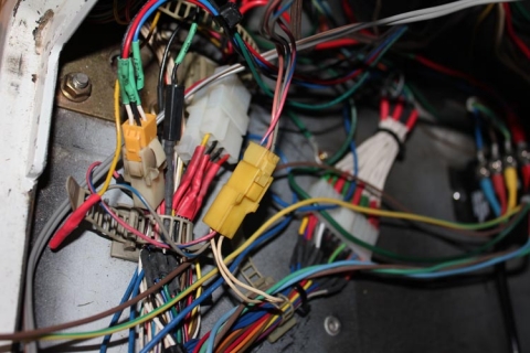
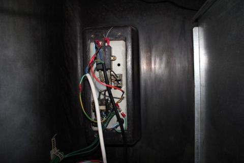
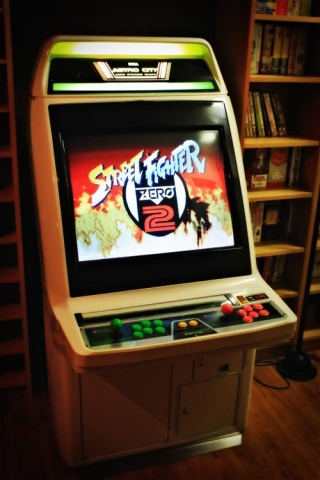
Overhauling the Sega Astro City – Part 13, final thoughts

Wow, who would have thought I’d actually get to this post, let alone finishing the project?

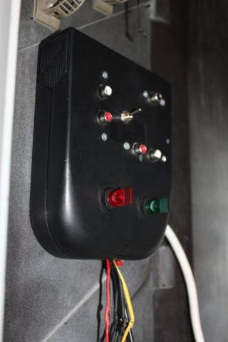
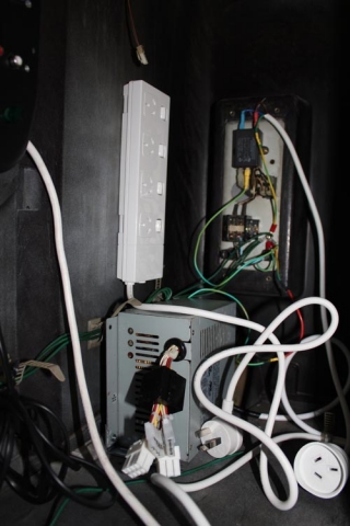
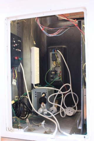
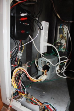
Well, the project was actually finished up a few months back, but I’m glad I got this post in there to round things off. This was a pretty big undertaking for me since it was my first arcade cabinet overhaul, and I have to say it went really well. The cabinet’s running beautifully and is happily playing anything I can throw at it. Once I have my Naomi IO and get around to building a converter for Model 2/Model 3 boards, I’ll be absolutely done.

So, with all this experience in mind, would I have done anything all that differently?

To be honest, not much went awry – I’m happy with the end result, and there have been no dramas with the setup. The only changes I’ll be making is that I’ll be splicing in button 4 for players 1 and 2 from the JAMMA harness into the JAMMA+ harness wiring to save swapping connections, but that’s it.

Thanks for sticking with this series of posts – if you want to check out the whole series there’s the Sega Astro City Overhaul tag, but for convenience, here’s the full listing:

Big thanks to the Aussie Arcade crew for helping with some daft questions throughout the process, it’s an amazing community of enthusiasts over there!

Now with this one sorted, I’ll have to see what my next project entails!

Overhauling the Sega Astro City – Part 12, replacing the monitor

Of all the aspects of the overhaul, replacing the monitor was the one I was dreading. The big 29″/68cm tubes are heavy, you have to be careful discharging the tubes and I was worried about scratching the new screen 🙂 To my surprise, it actually wasn’t too tricky.

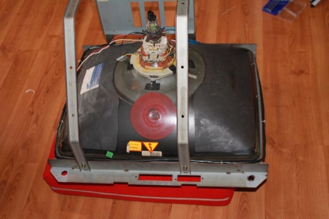
First up, the monitor (i.e. tube, chassis and mounting cage) had already been removed from the cabinet while I was rewiring it. I discharged the tube safely, grabbed a cushion off a nearby couch, and gingerly laid it face-down on the cushion so I could work on the cage and chassis without worrying about cracking the tube:

After using my capable screwdriver that will allow the shaft to bend at 45° and 90° angles and treating it like a wrench with a big phillips head screwdriver tip, I managed to remove the cage from the tube:

With that finished, here’s the chassis I removed the chassis from the cage before starting on the tube:

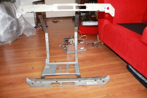
This left me with a nice empty cage to work with:

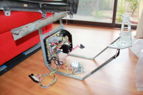
Next up, I grabbed the fresh, shiny Universal Chassis I ordered a while back for this job. I sourced the chassis from Jomac, who happen to be an amazing team to work with, provide expert advice and offer extremely competitive prices (in other words, they come extremely highly recommended). I then mounted the chassis to the cage like so:

Easy.

Next up came decasing the tube. I was able to source a Teac 68cm TV circa late-90s/early 00s from my parents that was perfect for the job – 68cm tubes are an almost 1:1 replacement for 29″ arcade tubes and are amazing quality. Paired with a Universal Chassis solution from Jomac, and I had a dual-resolution 15k/24k monitor for the price of a chassis, no need for factoring massive costs for sourcing arcade tubes.

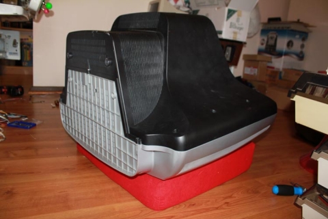
Anywho, the tube was safely discharged and I repeated the same process as before – gingerly lower the whole TV onto the cushion, then begin de-casing it:

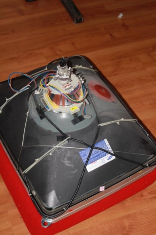
A bit of patient gruntwork later, and I’m left with the tube on the cushion awaiting the cage:

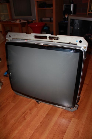
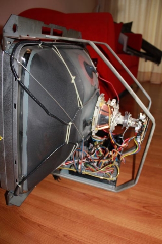
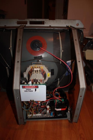
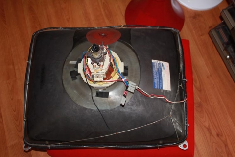
Simply mount the tube to the cage very carefully, ensure all the connections are solid, and I went about wiring up the degaussing coil, yoke connections, mounted the neckboard and ensured all the ground connections were fitted. This is the end result:

Front –

Side –

Rear –

The whole process probably only took 30-45 minutes, including discharging the tubes again at the start of the session – I had previously discharged them the day before and did it twice during the session to be extra careful with them.

All that’s left now is to plonk the monitor back in the cabinet, fit the front cover including the bezel, connect all the wires and run a smoke test, then the cabinet will be complete. Expect that report in the following (and hopefully final!) part in this series 🙂

As noted before, posts on the refurb are being done ad-hoc, so to keep track of the whole project, just use the Sega Astro City Overhaul tag, as the whole series will be added to it over time.
Overhauling the Sega Astro City – Part 11, rewiring the cabinet

This one is best told in pictures. Let’s start with the before:

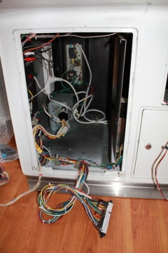
Looking inside the cabinet from the outside:

Closer up:

Power supply in focus this time:

Molex connections galore:

And the AC wiring, complete with heatshrink tubing and solder for the spliced connections:

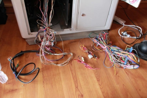
Here’s the aftermath, with all the control panel wiring intact (since it will be reused), and all the excess wiring removed:

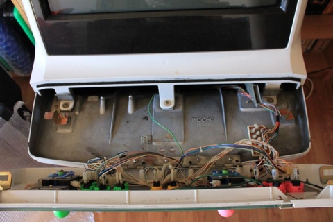
And for the sake of completeness, here’s the control panel without the bracket that houses all the molex connectors:

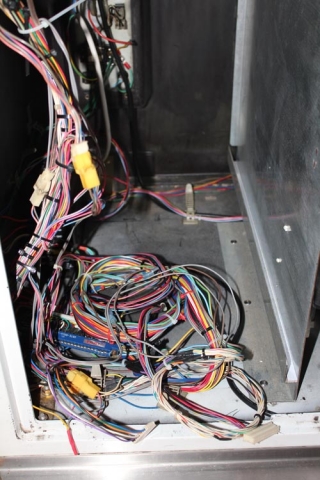
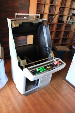
Now that all the wiring is out, next came the step of stripping everything out of the cab – the outer layers were removed that hold the bezel and speakers, exposing the fluro tube, and the monitor in its entirety (cage included) was also removed. To open up the insides for working, I also removed the partition that holds the PCB holder and separates the two halves of the cab. It really is looking like a shell now.

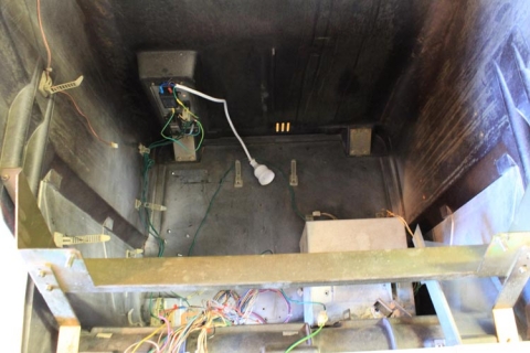
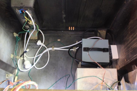
So, let’s start the refit – here’s a shot of the inside of the cab with only the new AC wiring present, with everything terminating to a female socket for ease of use:

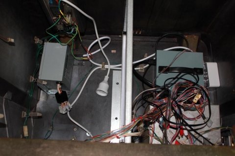
Next up, add the step-down transformer to the partition to the right:

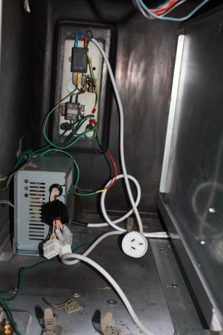
Add the partition to the cab and mount the SUN PSU into place; it’s positioned to allow for thick PCB boards, the MAME PCB or CPS2 setups, but still retain access to the unit for adjusting DC voltages:

… and another shot:

This next show shows the control box and the power board attached to the side of the cabinet:

The following closeups demonstrate when the control box and power board sit:

… and another:

… and another one:

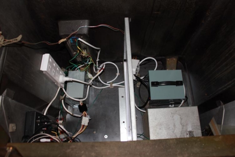
Almost there – the JAMMA harness has been added, molex connections are complete and cable-tied close to the frame, JAMMA harness is hooked up and some RCA connections have been added for the output on the control box:

And there we go – all finished and much neater than before!

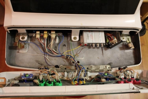
That takes care of the cabinet, but what about the control panel? We can’t forget that! Here’s a shot with the amp installed with all the wiring to the speakers and control box completed and the bracket re-installed:

And here’s the final shot with extra earth wiring grounding the monitor frame, amp, bracket and the coin slot chute/coin box:

Bit of a marathon run, but it came out really well. Next up – the new monitor!

As noted before, posts on the refurb are being done ad-hoc, so to keep track of the whole project, just use the Sega Astro City Overhaul tag, as the whole series will be added to it over time.
Overhauling the Sega Astro City – Part 10, mounting the MAME PC

I’ve talked before (here and here) on the MAME PC I’ve worked on as part of this project – today I have some images to show how I set it up.

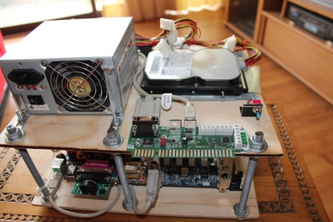
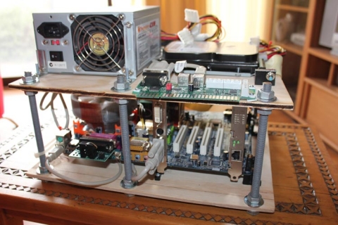
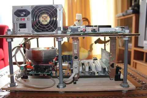
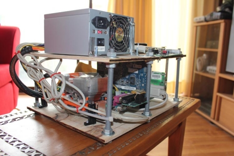
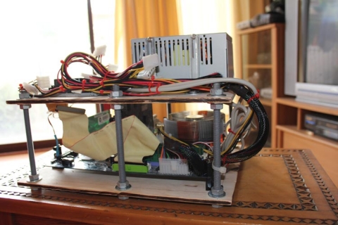
The aim was to have the PC mounted in a way that would easily allow me to swap it in/out of the cabinet like a PCB. To do this, I therefore needed to have it mounted on something, and due to the size of the chamber in the Astro City, I also needed to take space into account. I actually got the idea from some ghetto DIY arcade sticks I’d seen on the net, and I have to say I’m pretty happy with the end result.

It’s made up from a slab of MDF that I cut to size just slight larger than the motherboard with the mounting legs, with some extra give on the side where the accessories (graphics card, etc) stick out to allow for space for VGA adapters. The motherboard is propped up on PCB legs and screwed into the MDF to hold it in place. The top layer where the PSU, HDD and JPAC sit actually has two 80mm holes cut in a figure-8 shape that allows the CPU cooler to vent into the PSU and then have the PSU exhaust the air. To insulate the JPAC, I grabbed an old plastic VHS tape case and cut it to shape the JPAC with a rotary tool and that’s placed between the JPAC and the MDF. Small squares were then cut to act as plastic washers for the bolts so that the JPAC’s PCB wasn’t damaged when bolted down.

The poles supporting the structure were actually one long screw rod I got from the hardware store with an M10 width. Appropriate nuts and washers bind it for each layer, and I simply cut it to the necessary sizes using my angle grinder.

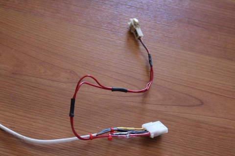
Everything was sized up, and bolts secure all the pieces of the setup, including cards in the motherboard, the PSU, JPAC and HDD. All the cables are secured using cable ties. The power button is routed to a DP3T switch I had lying around – simply flick it up, and it mimics the use of a power button.

All up, it works well, even if it is probably a bit rough 🙂 I like it though!

As noted before, posts on the refurb are being done ad-hoc, so to keep track of the whole project, just use the Sega Astro City Overhaul tag, as the whole series will be added to it over time.
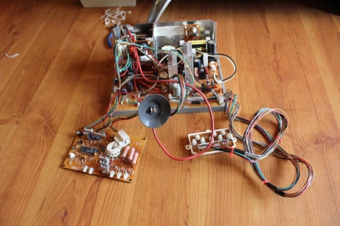
Overhauling the Sega Astro City – Part 9, customising the JAMMA harness

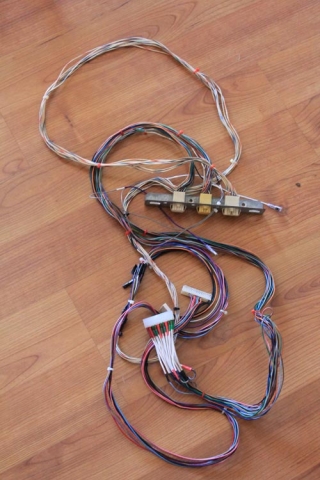
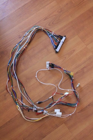
Because of the number of molex connections in the Astro City, and my desire to make this overhaul modular, I gave the JAMMA harness a hefty session or two with the soldering iron to get my desired outcome. The following is a full-length shot of the completed harness:
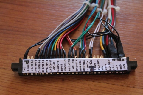
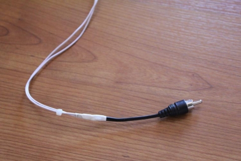
Audio mod

To fit in with the control box, the JAMMA harness takes the audio-out and puts it into an RCA connector. The positive or center pin takes the source from pin 10, or speaker +. The shielding/outer connection is actually a ground connection from any of the ground points on the harness. Astute observers will notice in the title pic that I have cabling coming from pin L, or speaker -, which I originally used in this mod, which was a bad idea! Had garbled audio and resetting PCBs. Thanks to Hewitson and the community at Aussie Arcade for that one, they steered me back in the right direction 🙂

-5v, ground and fan connections

This molex connection takes the -5v, ground and fan 12v output from the control box and feeds it into the JAMMA harness. This fan connection is another molex connector (2-pin) so that a fan can be connected if necessary, and as all the power comes from a separate connection to the PSU, it’ll remain constant regardless of the setup.

JVS to JAMMA power modification

The PSU in the cab is a SUN PSU, so the power connections are JVS standard. To accomodate this, I hacked a spare JVS extension cable and connected the +5v, +12v and ground to the relevant connections, and beefed up the wiring on the harness. By default it only had a single wire for each of these connections, so I added three additional wires to the +5v to help with the load for power-hungry games. I terminated the 3.3v wires on the extension cables with heatshrink tubing to keep it electrically safe.
Test and service buttons

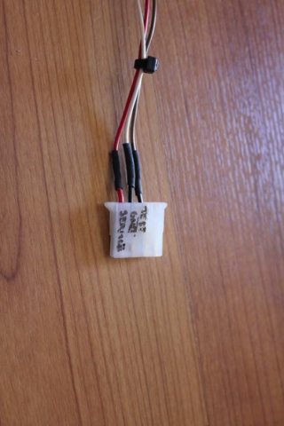
The test and service buttons are pushbuttons mounted underneath the control panel on Astro City cabs, so I terminated these connections along with a ground feed from the harness to allow easy connections. At the other end, I rewired the existing switches and cleaned them up so that they connected accordingly.
Coin slot connection

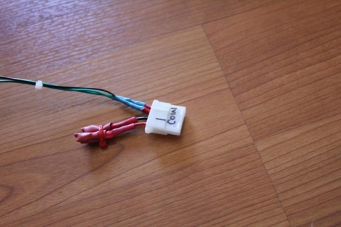
Similar to the service and test switches, the coin slot connection uses molex connections at either end. Inside the cab, the coin slot is also wired in parallel to a push button so that credits can be added without having to use coins. Handy, as I don’t have any ¥100 coins!

Controls

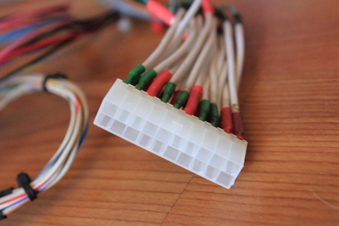
This was the biggest and scariest job – I chopped off the old molex connector after I manually used my multimeter to go through and check every connection on the molex connector, and its corresponding connection on the JAMMA harness. After doing this, I re-wired everything to the new JAMMA connector. The Astro City has every connection running through a couple of molex connectors, which then feed to a master connector that goes to the harness. The system worked, even if it was a little anally retentive, so I wanted to preserve this. This one connector took ages to put together, but I was really happy when it all worked 😀

Existing connections

This is a long shot of the wiring mounted underneath the control panel – the metal bracket holds three molex connections – one for player 1 controls, one for player 2 controls and one for the JAMMA+ (buttons 4, 5 and 6) for both players. On the bracket are also mounting points for up to three small push buttons, labelled for test, service and degauss. As the degauss switch is on the external panel from the chassis, it isn’t used in my setup.

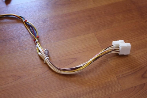
That final image is the female molex connector for the controls – a scary prospect to wire up! This feeds the P1 and P2 controls into the Astro.

The only other change I made was to have button 4 off the JAMMA harness for P1 and P2 be re-added into the master molex connector, and then have the female connector run extended lengths with quick-connects on that allow me to re-wire the control panel as required. This allows for quick and easy button changes when playing Neo Geo titles, for example.

As noted before, posts on the refurb are being done ad-hoc, so to keep track of the whole project, just use the Sega Astro City Overhaul tag, as the whole series will be added to it over time.